21 Boston – 07 – Post Tensioned Slab Pour

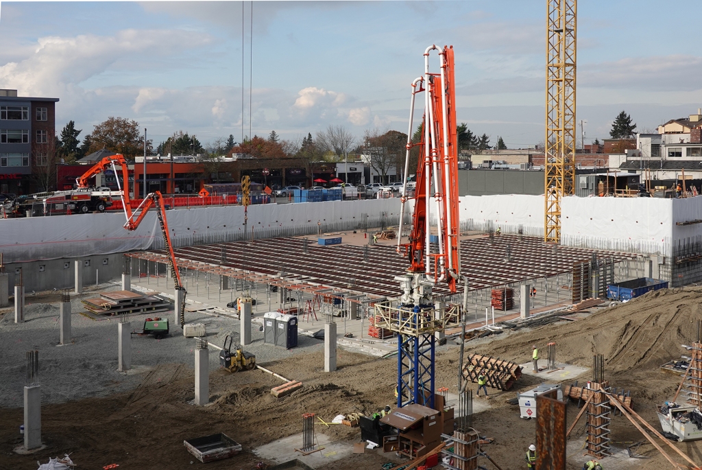
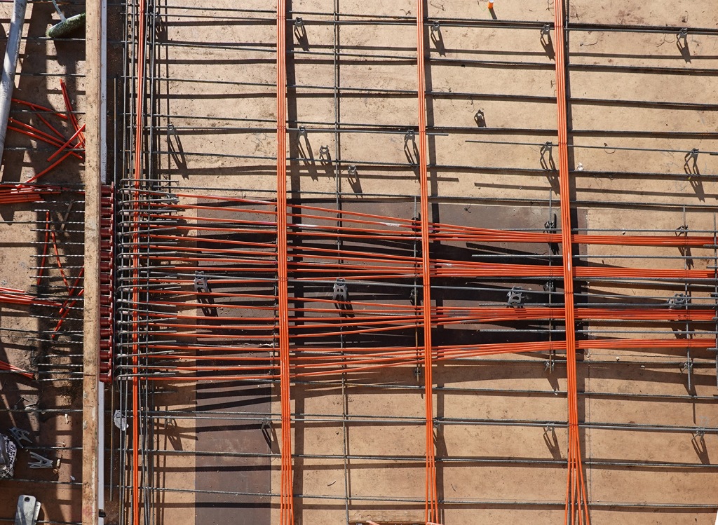
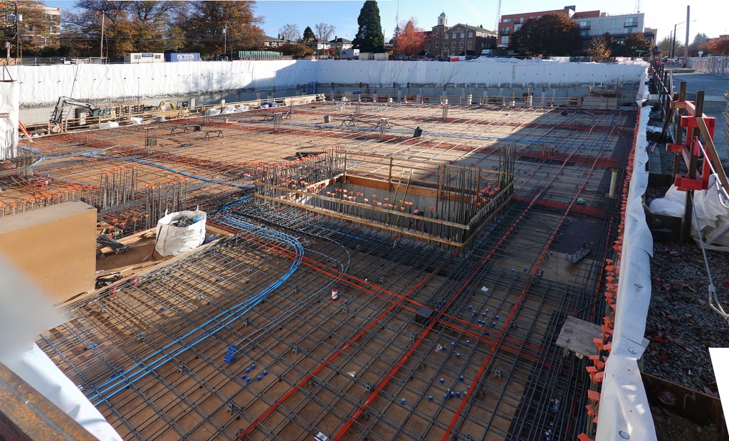
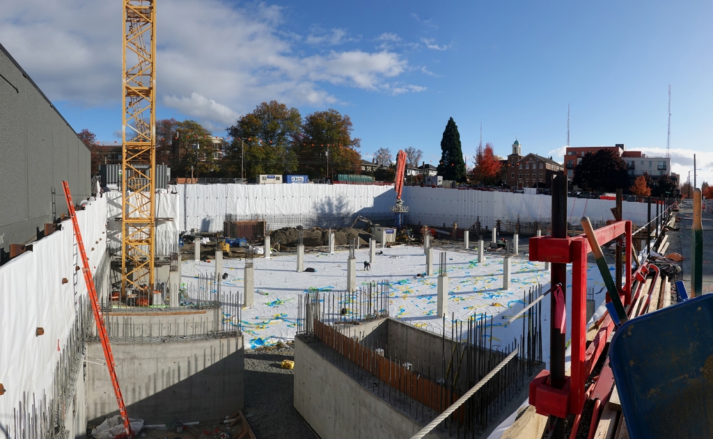
After a lot of painstaking formwork construction and the addition of a post tensioning reinforcement grid, the section 1 portion of the first structured floor was ready for concrete. This view, taken about the middle of November shows the formwork section to be poured, with the grade-level section 2 slab already in place to the left.

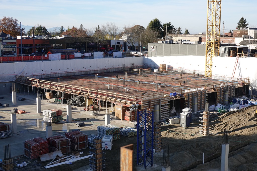
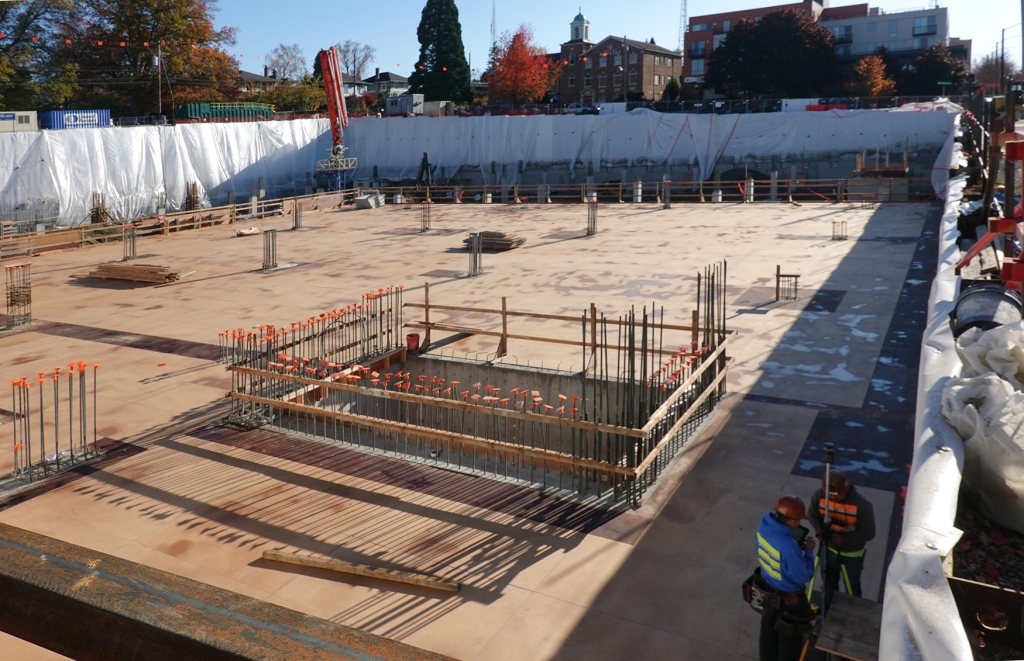
A quiet Thanksgiving day gave the crew a couple days off. Note that, in contrast to the photo above, the PT formwork for section 2 is now in place in the foreground, though it doesn’t have any reinforcing as yet.

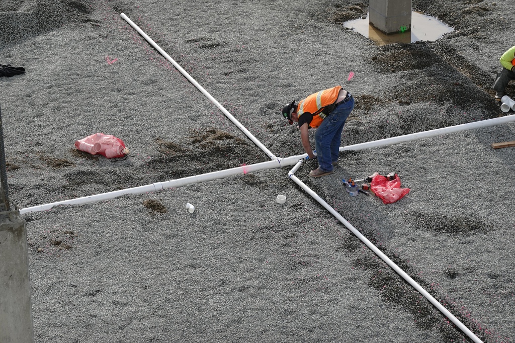
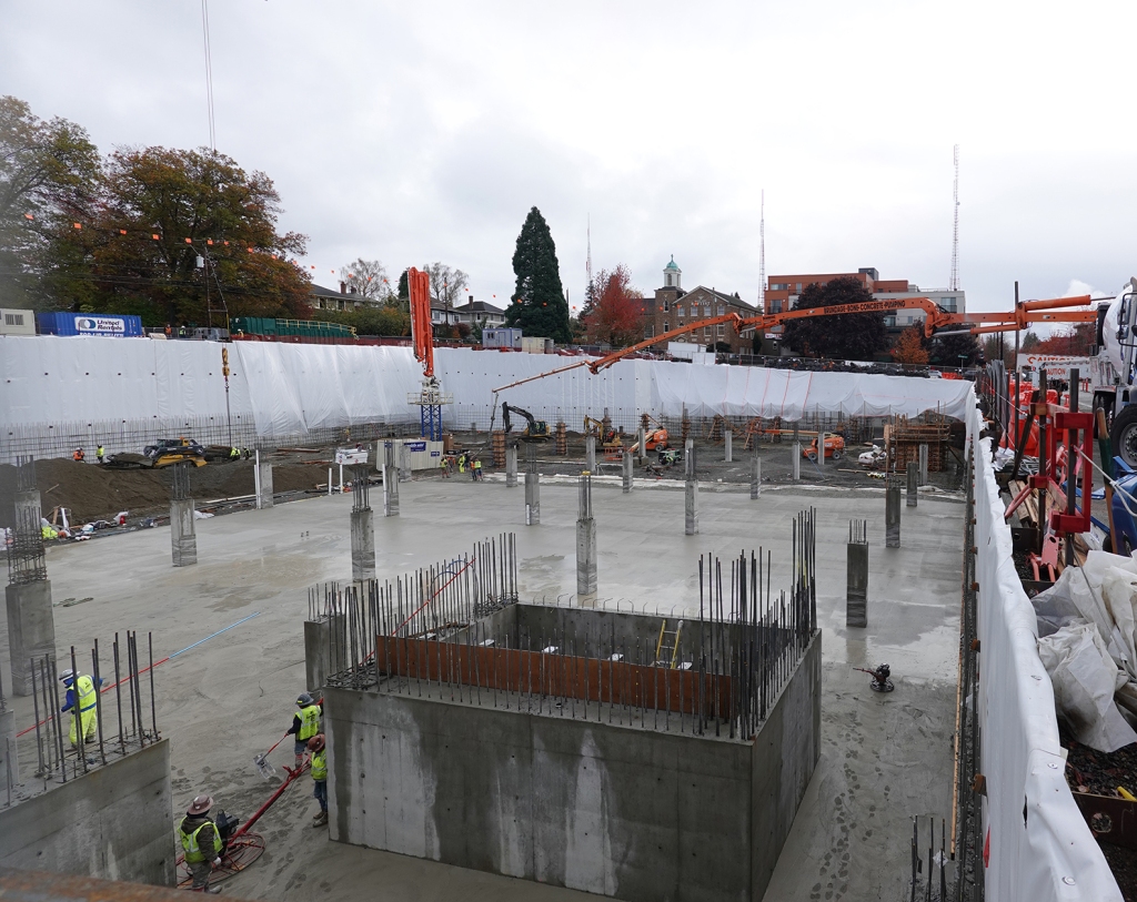
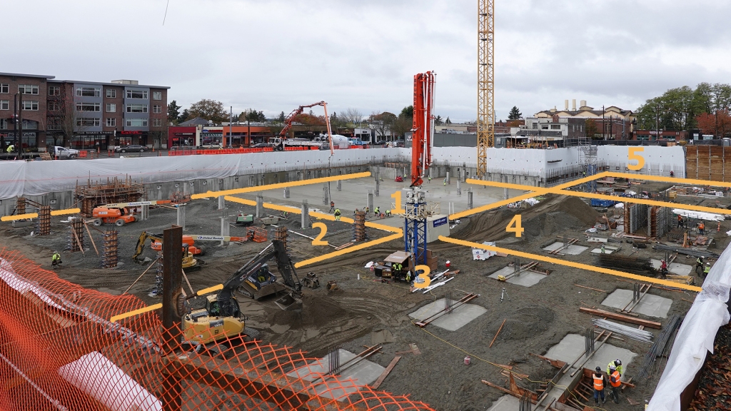
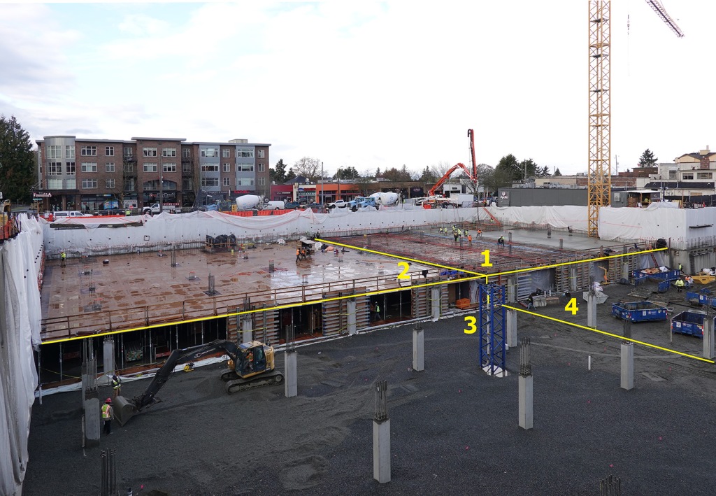
To give you a road map, I’ve outlined the first four sections: section 1 being poured, section 2 about to receive reinforcing grid, section 3 getting crushed stone, capillary break for its ground level slab, and section 4 providing support area for materials and equipment.

The pour starts up on Queen Anne Avenue, where pairs of concrete trucks deliver the mix to the pumping truck. A line of concrete trucks is staged around the block; and as soon as one has delivered its load, another replaces it.

It’s an intense area to be in, what with the large size of the equipment and the amount of vibration in a compact space.

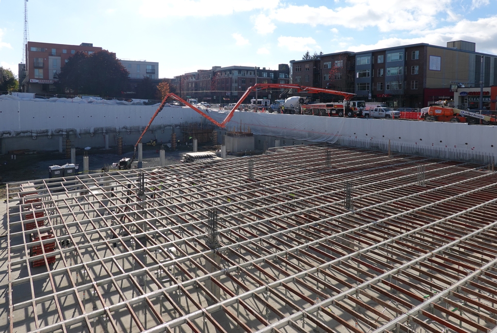
The pumping arm reaches a long distance and from this position the delivery seems delicate. The area in the foreground has already been poured and is getting final touches.

But when you get closer, you realize that the delivery end of the hose is where the action is. As you can see, the concrete is really fluid. Often additives are used to insure that it stays fluid all the way from the truck and does not clog the line.

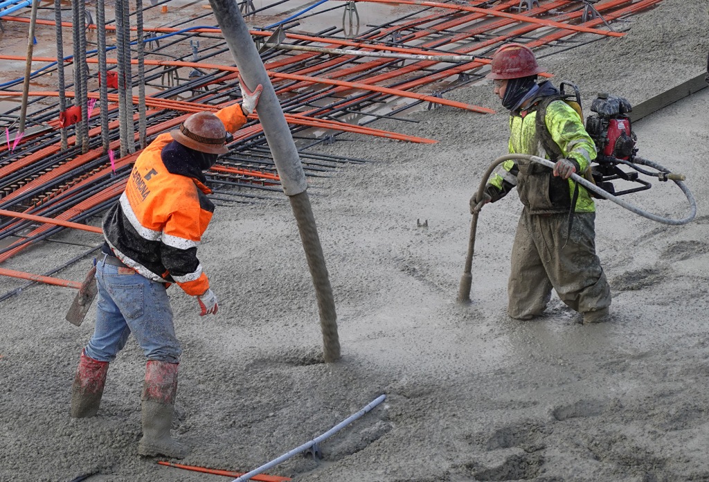
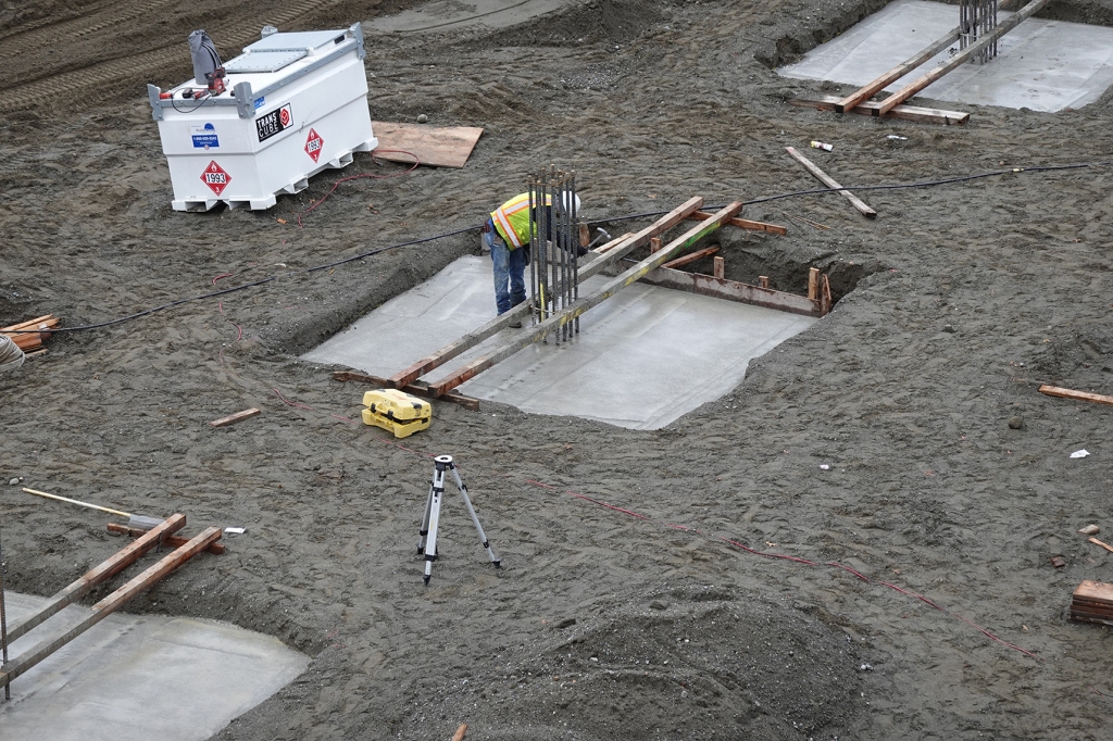
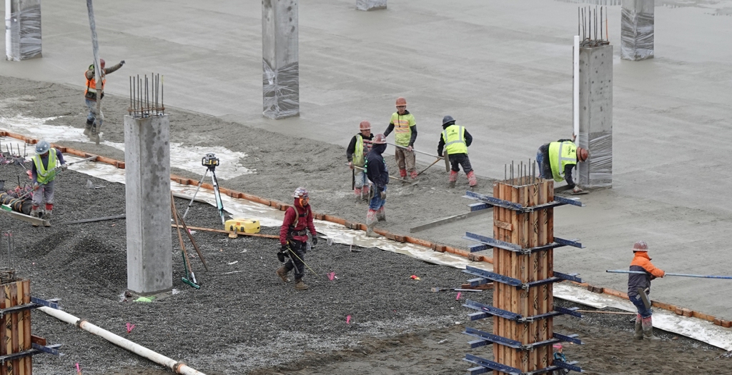
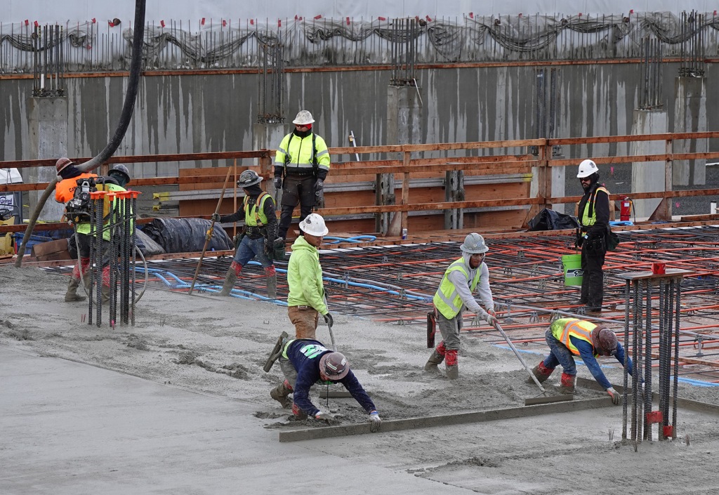
Before the smoothing crews get going a couple of key steps are required. The concrete has to be vibrated in ensure that it flows completely through the network of reinforcing and post-tensioning cables. Reinforced concrete works well only if it completely bonds with the reinforcing; and the vibration (man upper photo – right and lower photo – left) assures that it happens. One other key control element is assurance that the concrete is the correct thickness. The man in the green shirt on the right, below, is using a control stick with a gauge with which he frequently checks the depth.

Leveling, it turns out, is mostly a hand operation in the early stages because the concrete is too fluid to support any equipment. Here it involves two-man screed-board teams, supported by others who can add concrete to low spots as the leveling takes place.

In the case below, two men using individual screeding tools adjust the amount of concrete available to be leveled, adding and subtracting as the screed board is moved. Note that the guides are the screed board at 90 degrees on the right and the surface of the previously leveled slab on the left.

What is amazing, as shown in the picture below, is that the concrete is fluid enough that they’re in it up to their shins, and at the same time it’s firming up enough fast enough to be leveled and hold its position. Timing is everything; and the concrete is in charge.

Following at a discrete time and distance behind the pouring and screeding is the surface smoothing, using double-bladed riding machine that moves quickly in a variety of directions, followed by a smaller, hand-guided machine where the concrete has gotten firm enough for the worker to walk on the slab. Another worker over near the wall applies a final careful touch with a smoothing blade on the end of a 20′ long pole.

And finally, since the installation has been done in broad bands across the whole area, there’s some careful touch-up work applied at the joints.

Given how much hand work is involved, it’s impressive how well the finished slab turns out.

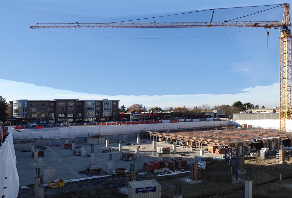
Finally, just a reminder that while today’s “excitement” was happening in section 1, sections 3, 4 and 5 have been busy as well. We’ll catch up with them soon.

21 Boston – 06 – PT Slabs

Immediately following the pouring of the Section 1 ground slab, construction began in preparation for the first PT (post-tensioned) slab one level above.

In an incredibly short amount of time the team erected the temporary support scaffolding in the northwest corner (above), and began the decking that would support the PT slab (below – far corner)

The scaffolding is spaced dimensionally for sheets of plywood. Special pieces of plywood are cut to fit around the future columns (areas where the reinforcing bars are sticking up above the deck level – below).

The grid is worked around unique elements, such as the elevator shaft shown here below, and the plywood decking will similarly be fitted up to the shafts. It’s important that when the slab is finally poured, the slab and shaft concrete should tie together.

This can be seen more clearly with the plywood deck in place (which was essentially done in a day with skill saws and nail guns).

Below you can see clearly how the plywood was crafted around the column areas and the large elevator shaft and pit.

Stepping back a bit (below), you can see two different, major operations going on at the same time. On the left, the vapor barrier is being installed over the crushed stone base in preparation for pouring the concrete of the next section of ground slab; and on the right, work has already begun on the reinforcing for the PT – post-tensioned – slab to be poured there.

Here are a couple of view of that work up on the deck.

As can be seen in these two views, there are a lot of different types of reinforcing being installed. The smaller, black bars are the normal reinforcing that strengthens concrete slabs, one set near the bottom of the slab, and another set near the top. In addition to these, however, are a set of what look like orange reinforcing bars. These are actually plastic-sheathed steel cables. Also noticeable is the fact that they don’t like flat but are draped higher near the columns and lower between columns. This has lot to do with how PT slabs work structurally.

In a PT slab, after the concrete is poured and has cured or set up a few days, the post-tensioning bars are pulled from each end, increasing the tension on them. This has two major effects on the slab. One is to cause the draped bars to want to straighten and raise up in the areas between columns. They can’t do this of course because of the weight of the concrete; but the stress they put on the concrete helps it resist the weight of parked cars and other loads on the slabs. The other effect is that the tensioning increases the compressive strength of the concrete in general, which increases its normal efficiency and allows the overall slab thickness to be reduced, saving materials. Working together, these two effects make for very strong floors.

Below is a look at the ends of the post tensioning rods (left side) where, if you look closely, you can see that the individual rods are threaded. These are the locations a hydraulic stressing ram will pull on them to increase the tension.

Notice also the little metal gadgets that look like spiders, but are often called chairs, that hold the reinforcing systems up off the deck. This is to prevent the reinforcing from touching the deck which would expose the reinforcing under the slab when the decking is removed from below and make the reinforcing vulnerable to corrosion.

One other critical detail is the wire that is being twisted around the places where the reinforcing bars cross over each other. This keeps the grid generally in the right place when the concrete is being poured so the structure will perform as it has been designed.

Then finally two more layers are added. First, the layer of electrical conduit (blue and gray) that goes on top of the bottom layer of reinforcing.

And then the top layer of reinforcing. The idea here is that the layers of reinforcing perform best when they are near (but not literally at) the upper and lower surfaces of the concrete; and other elements, like conduit, do best near the “neutral axis” (center) of the slab thickness where any effect they have on the structure will be reduced.

That’s a lot of energy going into Section 1, the northwest corner of the project; but it doesn’t mean that other areas are being neglected. Right next door, in Section 2, the ground slab is being poured so that it will be ready for the scaffolding and decking teams to start there work for the next PT slab.

That slab pour starts, of course, up at street level with concrete delivery and pumping.

Farther round the site, in sections 3, 4, and 5, the exterior wall reinforcing is being installed in preparation for the shot-crete walls. These walls need to be completed up to the level of the next floor before the PT deck is constructed so the wall and floor can be tied together.

And overhead – and often out of sight / out of mind – the tower crane lifts all sorts of things into and out of the site – a necessity when you’re working “in the hole” and can no longer drive in and out. Lifting things overhead is serious safety work; and a senior rigging director supervises every lift (steps 1 -4) and blows a loud whistle so everyone on the site is aware that loads are travelling above.

Finally, a look at Sections 1 and 2, ready for the next steps. In this photo (below) you can see that the scaffolding elements have already been stacked on the new ground slab in Section 2, ready to be set up.

And here in Section 1, the PT slab is nearly ready to be poured

This project is moving !

21 Boston – 05 – Concrete Arrives

There are a lot of different things going on in the various sections of the site; but the major efforts are focused on the Northwest corner, in the far left of this full-site picture.

Preparation required the forming and pouring of a major elevator shaft, seen here in the foreground, along with having the perimeter walls in place up to the next level.

And as that got poured in place, the spreading and leveling of a bed of crushed stone to support the floor slab to come was done by small earth movers and hand-spreading.

This included burying under-slab drainage for later moisture control.

At the same time, in the area for future phases, column footings were being poured into earth-forms. In good, stable soil, choices are available for forming footings. As you can see with this one, one side is formed with plywood, but the others just use the earth itself.

Special columns (blue) and footings were also installed to support the two concrete placing booms. These columns will grow with the project but eventually be removed, leaving the footing behind.

How does the concrete get to all these locations ? It flies across the site courtesy of a pumper truck sitting up on Queen Anne Avenue to the left.

Back in the northwest corner, preparations are being made for the first large pour of floor concrete. This involves placing a continuous layer of vapor barrier (white plastic) on top of the gravel to keep any soil moisture from migrating up into the floor slab.

And then, boom!, an acre of concrete slab gets pumped in by truck and smoothed out in a day, some by machine and some by hand.

Pouring this much concrete slab in a day requires delicate timing. Concrete starts to cure / harden as soon as it is poured. While the curing process is not instantaneous, it is relentless. The big distribution has to be moved and leveled while it is fluid but the surface smoothing has to take place after it is relatively stable, but, BEFORE it fully hardens.

In the photo below the workers are pushing and rough-floating the last row to be placed in this first pour. It’s amazing to think that they’re wading in a material that an hour or so later they’ll be walking on and smoothing out.

Closer to the NW corner the workers are smoothing out footprints left from when the concrete was still too soft. This requires a combination of machine blade and hand blade smoothing.

Finally, here’s a view from the opposite side of the site that shows all the phases of concrete work going on at the same time.

And here, that same view, I’ve shown the 5 construction-phasing sections of the site outlined. Compass Construction’s plan is, in general, to work in a counter-clockwise direction from section 1 to section 5 with each of the required steps in sequence.

Just for reference, each of these sections is roughly an acre in size.

Next time we’ll see the construction of the first post-tensioned slab of the next level up in section 1, along with the base slab in section 2.